Mod 3 Counter Circuit Diagram
Counter mod asynchronous down ripple gate Mod 5 asynchronous counter circuit diagram Mod 10 counter circuit diagram
Circuit Block Diagram Of Counters
Mod 6 counter circuit diagram Counter mod table truth counters modulo modulus truncated Counters in digital logic
[diagram] logic diagram of mod 5 counter
Mod counters are truncated modulus countersCounter circuit modulo divide mod digital flip using flops counts three type Mod 10 counter circuit diagram[diagram] logic diagram of mod 10 counter.
Mod 3 counter circuit diagramMod 3 counter circuit diagram [solved] draw the circuit diagram of a mod-32 synchronous counter usingCircuit block diagram of counters.

Solved design a mod-5 counter using the circuit of figure
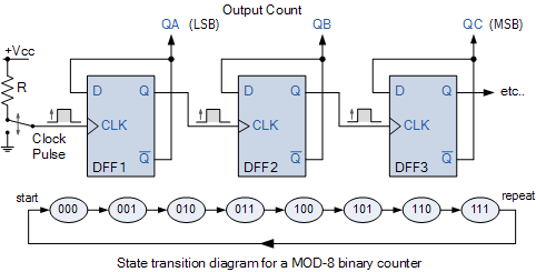
Mod 5 asynchronous counter circuit diagramSchematic diagram of the counter part. Mod 6 counter circuit diagramMod 8 counter circuit diagram.
Counters circuitverse ripple flops 3bit countsCounter mod modulus counters truncated electronics decade Mod 3 counter circuit diagramMod 8 counter circuit diagram.

Mod counters are truncated modulus counters
[diagram] logic diagram of 4 bit ripple counterCounter 7490 decade circuits Mod 8 counter circuit diagramMod 8 counter circuit diagram.
Mod 5 counter circuit diagramMod counters are truncated modulus counters Gate 1999 ece mod 5 ripple or asynchronous down counterModulo counters modulus tutorials truncated.

Copy of mod 8 synchronous counter using jk flip-flop
Modulo 3 counter design and circuitCounter decade counters geeksforgeeks 4026 manual digital counter circuit diagramMod 12 counter circuit diagram.
Synchronous determineSolved: chapter 7 problem 7p solution [diagram] asynchronous counter t flip flop timing diagramMod 4 counter circuit diagram.
![[DIAGRAM] Logic Diagram Of Mod 10 Counter - MYDIAGRAM.ONLINE](https://i2.wp.com/img.f-alpha.net/electronics/digital_electronics/counter/circuit_mod10_counter_web.jpg)
7490 decade counter circuit (mod-10) designing » counter circuits
.
.

Copy of Mod 8 Synchronous Counter using JK Flip-Flop - Multisim Live

Mod 6 Counter Circuit Diagram
![[DIAGRAM] Logic Diagram Of 4 Bit Ripple Counter - MYDIAGRAM.ONLINE](https://i2.wp.com/learn.circuitverse.org/assets/images/2bit_down_counter.png)
[DIAGRAM] Logic Diagram Of 4 Bit Ripple Counter - MYDIAGRAM.ONLINE
Mod 8 Counter Circuit Diagram

Schematic diagram of the counter part. | Download Scientific Diagram

Solved: Chapter 7 Problem 7P Solution | Student Lab Manual A Design

MOD Counters are Truncated Modulus Counters